

OEM Rotary Valve Selection and Customization Guide
2026-11-04
Every OEM engineer knows the feeling: you find a rotary valve that looks perfect on paper, but it doesn't quite fit your machine's envelope, material, or duty cycle. Then the customization conversation starts—and it can go sideways fast. That's why the right selection framework matters before you ever send an RFQ. In this guide, we walk through the criteria that actually move the needle for OEM applications: rotor clearances, seal materials, inlet/outlet geometry, wear protection, and the hidden cost drivers in custom configurations. Whether you're specifying for powders, pellets, or sticky slurries, small decisions here ripple through your entire assembly. At AVM, we've seen too many projects stall because the valve was treated as a commodity instead of a co-engineered component. This guide shares the practical questions our engineers ask on every OEM inquiry—so you can spec with confidence, shorten lead times, and avoid retrofits later.
Matching Rotor Geometry to Your Hardest-to-Handle Powders
Powders that float on the surface or clump the moment they touch liquid rarely respond to a one-size-fits-all rotor. A steep-pitched, open-channel rotor pulls hard-to-wet solids downward quickly, creating a deep vortex that drags even lightweight fumed silica below the surface before it can dust. A saw-tooth or slotted rotor, on the other hand, trades some of that drawdown force for intense localized shear, which breaks apart waxy agglomerates and high-oil-content powders once they've been incorporated.
Cohesive materials like xanthan gum or carbomer put that match to the test. Here, rotor diameter relative to vessel width matters as much as tooth shape. A rotor that sits too small leaves dead zones where powder packs against the wall; too large and the batch climbs the shaft. Matching the geometry to the powder's failure point—how it fractures under shear—lets you run at higher powder loadings without stalling the drive or burning out the motor.
Rather than chasing higher tip speed, look at how the rotor's leading edge approaches the batch. Rounded profiles tend to push powder away, while sharp, square-cut teeth slice into the bed and open channels for liquid entry. For fibrous or needle-like powders, wider channels with fewer teeth prevent bridging across the rotor face, keeping the mix moving long enough for full wet-out.
Seal Selection: The Overlooked Factor That Decides Valve Lifespan
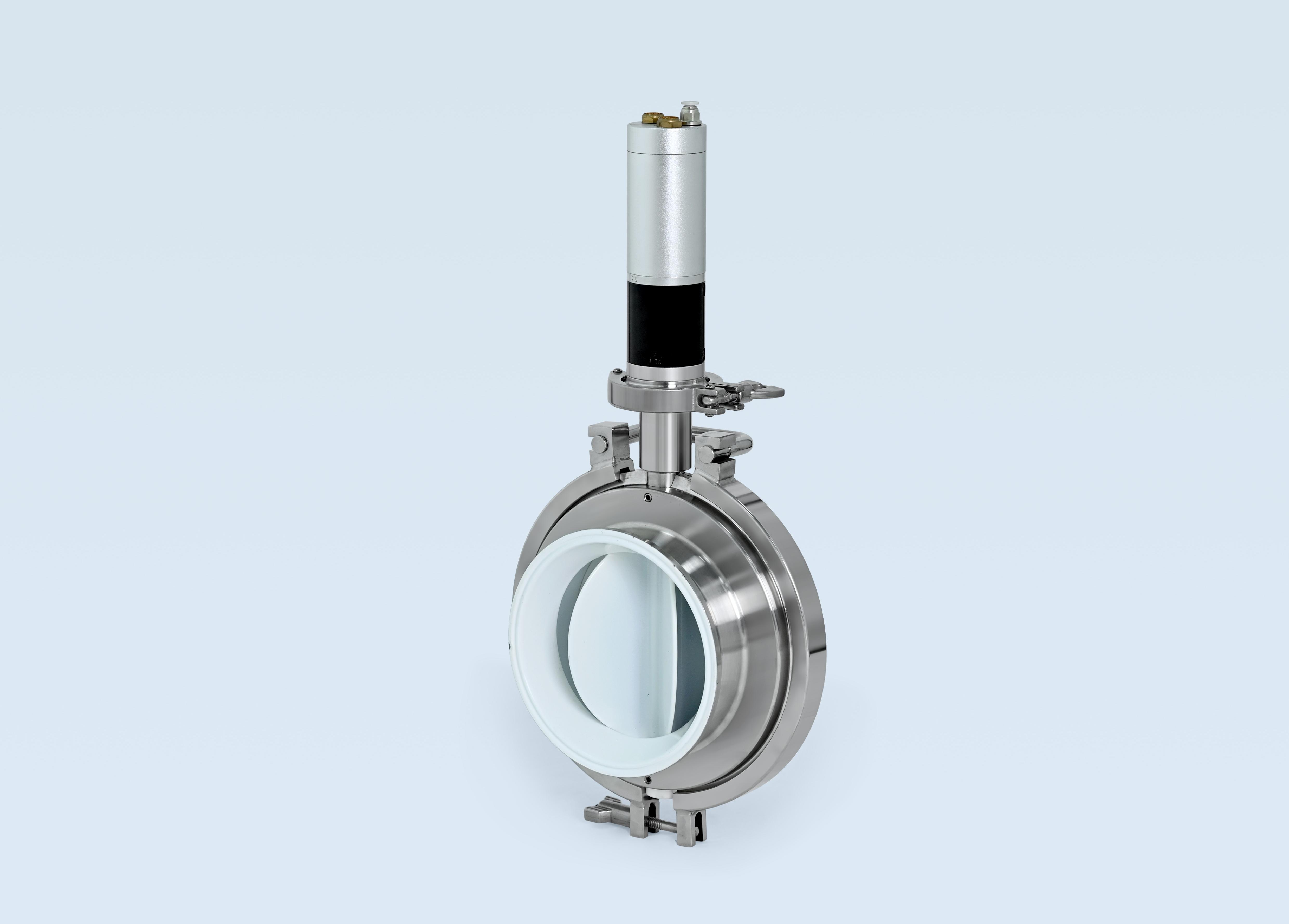
Walk through any valve specification meeting and you will hear endless debate over body material, pressure class, and Cv ratings. What you rarely hear is a serious conversation about the seal. Yet the seal is the one component that touches the process fluid continuously while enduring cyclic stress, thermal swings, and chemical attack. Pick the wrong seal and even a premium valve will leak, stick, or fail long before its time. I have seen stainless steel valves retired after only a few hundred cycles because someone threw in a standard PTFE packing that cold-flowed and extruded under pressure. The valve body was fine. The seal was never given a chance.
Seal selection is not about grabbing the default graphite or PTFE option off a datasheet. Different materials behave radically differently depending on temperature, media, and mechanical load. PTFE offers superb chemical resistance but suffers from cold flow and poor heat dissipation. PEEK handles high pressure and temperature but demands higher torque and can score shafts. Graphite excels at high temperatures but sheds particles and can contaminate clean media. Elastomers like FKM or EPDM seal well at low temperatures but swell or degrade in the wrong chemicals. Beyond material, you have to account for PV limits, extrusion gaps, stem finish, and whether the application is rotary or linear. A seal that works perfectly in a quarter-turn ball valve may fail quickly in a rising-stem globe valve cycling every few minutes.
The smart approach is to treat the seal as a design element, not an afterthought. Start by mapping the actual duty cycle: temperature range, pressure spikes, chemical composition, particulate content, and how often the valve moves. Then match those conditions to a seal with the right balance of elasticity, creep resistance, and friction. Sometimes that means using a spring-energized PTFE seal instead of a plain lip seal, or switching to a filled PTFE blend to reduce extrusion. In critical applications, a short bench test with the real process fluid can reveal failures that datasheets never predict. Spending an extra hour on seal selection often adds years to valve lifespan, and that is a trade-off worth making.
Sizing Without Guesswork: Avoiding the Most Common Throughput Miscalculation
Most throughput estimates fall apart because teams anchor on peak capacity instead of sustained behavior. They take the vendor's maximum IOPS, multiply by some optimistic concurrency number, and call it a day. But real systems throttle, queue, and degrade long before the spec sheet says they should. The first step to accurate sizing is measuring your actual workload's latency distribution, not its theoretical ceiling.
Another frequent mistake is treating throughput as a single static value. Traffic patterns shift: batch jobs spike at midnight, read-heavy hours alternate with write bursts, and cache hit ratios fluctuate. A sizing model built on an average request rate will under-provision during those cliffs. Break your load into distinct profiles—steady-state, peak, and burst—and size for the 95th percentile of each, not the mean.
Finally, don't ignore tail latencies. A system that handles 10,000 requests per second with 99% of responses under 50ms can still collapse if the remaining 1% take two seconds and hold connections open. Those slow requests consume thread pools, file descriptors, and database locks, multiplying the effective load. Sizing without a tail-latency budget is guesswork dressed in arithmetic.
Beyond Cast Iron: Coatings and Alloys That Survive Abrasive Service
Cast iron has long been the default choice for abrasive environments, but it's not the only path—nor always the smartest one. When material loss from sliding, impact, or high-velocity particle streams becomes a daily operating cost, engineered coatings and specialty alloys start to look less like an upgrade and more like a survival strategy. Think of a mining chute lined with a chromium carbide overlay, or a pump impeller rebuilt with a tungsten carbide-infused composite. These aren't just thicker skins; they're carefully designed microstructures that shed abrasive particles instead of absorbing their energy.
The real advantage shows up when you stop chasing a single magic material and start matching the wear mechanism to the treatment. High-stress grinding abrasion chews through AR plate, but a fused tungsten carbide layer can shrug off the same punishment for months longer. Sliding wear under low load might only need a plasma-sprayed ceramic coating that beats cast iron by reducing friction while keeping the substrate tough. Then there are the cast-in-place alloys—high-chrome white irons and nickel-hard variants—that offer a middle ground, combining the ease of a casting with hardness profiles once reserved for weld overlays. Each option has a failure mode, of course; the trick is knowing whether your process eats by gouging, polishing, or eroding.
Maintenance teams are increasingly mixing these approaches. A coal pulverizer might get a ductile iron housing for shock resistance, but its internal vanes get a laser-clad cobalt-based alloy where the coal stream hits hardest. It's not about replacing cast iron everywhere—it's about putting the expensive, wear-resistant material only where the wear actually occurs. That kind of selective hardening often pays for itself within a single outage cycle, especially when downtime costs dwarf material costs. The question isn't whether cast iron can survive; it's whether you can afford to keep finding out the hard way.
Sanitary Rotary Valves: Designing for CIP and Eliminating Contamination Traps
The core challenge in sanitary rotary valve design lies not in the basic function of metering product, but in how every surface, gap, and joint behaves when the line goes through a clean-in-place cycle. A valve that looks clean during dry operation can mask product buildup behind the rotor endplates, inside the shaft seal area, or along the housing bore. For true CIP compatibility, the rotor tips and housing interior need a surface finish of 0.8 µm Ra or better, with all internal radii opened to avoid sharp corners where powder can pack. The rotor should be designed to lift out or swing away without tools, and the clearances between rotor and housing must be tight enough to prevent product from migrating into dead zones, yet loose enough to let cleaning fluid reach every wetted surface.
The most common contamination traps are the shaft penetration points and the endplate sealing areas. Standard lip seals or packed glands create crevices that cannot be cleaned by spray or flood. A better approach is to use a double mechanical seal with a flush chamber, or a sterile barrier design where the shaft is isolated from the product zone by a flexible diaphragm. Some valves eliminate the shaft penetration on the product side entirely by driving the rotor through a magnetic coupling, although this adds cost and torque limitations. For CIP effectiveness, every seal must be visible or easily accessible for inspection, and O-ring grooves should be designed with a square or dovetail cross-section that holds the ring in place without creating an undercut that traps residue.
Beyond individual component design, eliminating contamination traps requires thinking about the valve in the context of the surrounding pipework. The inlet and outlet transitions must be smooth and self-draining, with no ledges or weld spatter. If the valve body includes a purge or vent port, that port must be part of the CIP circuit, not a blind pocket. Validation should include riboflavin testing on the actual product-contact surfaces after a simulated soiling run, not just a pressure test. Only when the valve can be cleaned with the same time, temperature, and chemistry as the rest of the line can it be considered truly CIP-ready.
Drive and Sensor Integration: Building a Valve That Talks to Your Control System
Most valve assemblies still treat the actuator and the sensor as separate afterthoughts. You bolt a drive onto the stem, wire a couple of limit switches back to the PLC, and hope nothing drifts. Once you integrate the drive electronics and the position feedback into the same housing, the valve stops being a dumb final element. It can report its own torque profile, stroke time, and cycle count without a separate I/O card.
The real payoff shows up during commissioning and troubleshooting. A valve that streams its actual stem position and motor current lets you spot a sticking seat or a degrading capacitor before it locks up the line. Instead of walking out to the rack with a meter, you pull the data through the same block that handles your analog output command. Modbus TCP or PROFINET are common, but even a simple 4–20 mA HART channel can carry secondary variables if the drive firmware is set up correctly.
One detail often overlooked is timing. If the drive’s internal sampling loop isn’t synchronized with the control system’s scan, you’ll see jitter in the feedback and false alarms in the historian. Set the update rate to something the controller can actually consume, and map only the parameters you’ll act on. A clean tag list matters more than raw bandwidth.
FAQ
Focus on rotor tip clearance, material hardness, and replaceable wear components. Abrasive powders will quickly erode standard cast iron, so look for hardened steel or ceramic-coated rotors and a housing with adjustable or sacrificial wear plates.
High pressure differentials cause air leakage past the rotor, which can disrupt downstream feeding. For systems above 10 psi, you'll need a valve with tighter clearances, a higher number of vanes, or even a twin-rotor design to maintain an effective seal.
Yes, but you must specify surface finish, material compliance, and cleanability. Opt for 316 stainless steel bodies, polished internals to at least Ra 0.8 µm, FDA-approved seals, and a design that allows tool-free disassembly for CIP or manual washdown.
The biggest mistake is matching the valve's physical inlet size to the upstream hopper without calculating actual throughput. You need to account for rotor displacement per revolution, fill efficiency (which drops with speed and material flowability), and the motor's turndown ratio, not just the flange diameter.
Closed-end rotors are used when the pressure differential is significant and you need to minimize blow-by, but they trap material between the shroud and rotor end. Open-end rotors are better for sticky or fibrous materials because they prevent product build-up near the end plates, at the cost of higher air leakage.
For fine, penetrating powders, packing glands with purge ports are often insufficient. Use air-purged mechanical seals or double lip seals with a continuous low-pressure air barrier. This prevents powder from migrating into the bearings and causing premature failure.
Rarely without modifications. OEM footprints vary in flange drilling, rotor length, and shaft extension. Provide the existing valve's dimensional drawing, rotor diameter, and mounting orientation to the manufacturer, and request a dimensional compliance check before assuming a drop-in fit.
High rotor speeds increase shearing and impact at the inlet, which can crush or break fragile granules. For low-degradation feeding, run the valve below 20 RPM and specify a larger rotor displacement with a shallow pocket depth to reduce the pinch point and tumbling action.
Conclusion
Getting an OEM rotary valve right starts with the powder itself. Rotor geometry isn't a catalog pick; cohesive, sticky, or floodable materials demand different vane depths, tip clearances, and even rotor profiles to avoid bridging or blow-by. Seal selection often kills performance long before wear does—lip seals, air-purged glands, and mechanical options each trade leakage control against friction and maintenance burden, and the wrong choice at a pressure boundary will show up as rotor stalls or rapid housing wear within weeks. Throughput sizing trips up many teams because they take nominal displacement at face value. You have to correct for fill efficiency, rotor speed limits, and product aeration, otherwise the valve either starves the process or forces you to run at a speed that makes leakage worse.
Material choice goes far beyond cast iron when abrasive or corrosive powders are involved. Hard-facing overlays, tungsten carbide coatings, or chrome oxide treatments on rotor tips and housing bores can double or triple service intervals, but only if matched to the specific wear pattern. For sanitary applications, CIP is a design requirement, not an option: internal contours need to drain fully, seals must sit flush with no crevices, and quick-access endplates or split housings become non-negotiable. Drive and sensor integration turns a basic feeder into a process instrument. Variable-frequency drives with feedback on rotor speed, differential pressure, and temperature let the valve report its own health, detect stalled conditions, and adjust feed rate in real time. Customization means wiring these choices into a single coherent package rather than stacking independent options.
Contact Us
Contact Person: Ananda
Email: [email protected]
Tel/WhatsApp: 8619016718200
Website: https://www.wzaomi.com